What is the structure of new energy transformers in new energy products?
Generally speaking, new energy transformers can be classified according to its use, structure, number of phases, cooling mode and cooling medium. According to the use of the main power transformer (Power Transformer), regulator (Voltage Regulator), instrument transformer (Instrument Transformer), special purpose transformers.
New energy vehicle drive motor technology, according to the number of phases mainly single-phase transformers and three-phase transformers. According to the number of windings are mainly autotransformers (Autotransformers), double-winding transformers and three-winding transformers according to the core structure is different, the transformer can be divided into heart transformer and shell transformer. According to the cooling medium and cooling different transformers can be divided into air-cooled dry-type transformers, oil for the cooling medium of oil-immersed transformers and gas for the cooling medium of the gas transformer. 2. the structure of the transformer transformer’s main components are: the core, windings, transformer oil, tanks and accessories, insulating casing. Core and winding is the main components of the transformer, known as the body; tank as a transformer shell, play a role in cooling, heat dissipation and protection; bending transformer oil both play a role in cooling, but also play the role of insulating medium; insulating casing mainly play a role in insulation. The following is a brief introduction to the main components of the transformer.
(1) transformer core material
1.) core material. Iron core is the main magnetic circuit in the transformer, but also the mechanical skeleton of the set of windings. The core is made of soft magnetic material with high permeability, hysteresis and eddy current loss. Transformer development in the early stage, the use of ordinary iron as a core material, and later developed a hot rolled magnetic steel as a core material. 1934 Gauss invented a cold rolled grain oriented silicon steel sheet, and gradually replaced the hot rolled silicon steel sheet. 1968, Japan’s New Nippon Steel Corporation first developed a high permeability silicon steel sheet – Hi-B grain oriented silicon steel sheet, its unit loss and excitation ampere-turns are smaller than the ordinary grain oriented silicon steel sheet, so it is widely used in the field. In the 1980s, lower-loss silicon wafers with refined magnetic domains (by laser irradiation or mechanical indentation) were introduced. The most important properties of silicon wafers are the loss per unit mass and the magnetic permeability of the material. Cold rolled grain oriented silicon steel sheet loss than the hot rolled silicon neighbourhood sheet has a great reduction, so the current power transformer almost all use cold rolled grain oriented silicon steel sheet as the core material.
Non-product alloy is cold rolled grain oriented silicon steel sheet after another core material, which is characterised by high permeability, no-load current and no-load loss than the orientation of silicon steel sheet is greatly reduced. In the mid-1960s, foreign countries have begun to study amorphous material, in 1974 began to be used in transformer cores, the United States CE company first used amorphous alloy to manufacture a 25kV-A transformer is now 2500kV-A amorphous alloy core transformer. However, due to the low saturation flux density of amorphous alloy, the thickness of thin processing difficulties, high material prices, so in the manufacture of large-capacity transformers have not been used in large quantities.
At present, most of the transformer core by the thickness of 0.15 ~ 035mm cold rolled silicon steel sheet stacked and become, silicon steel sheet in the silicon content of about 4%. Silicon steel sheet surface is generally covered with a layer of high electrical insulation insulating film, insulating film has a very high insulation resistance and good mechanical properties. According to the data statistics, developed countries transformer iron consumption accounted for about 4% of the total power generation, so reduce transformer iron consumption is to improve the efficiency of the grid important measures. Reduce iron consumption mainly by increasing the silicon steel sheet silicon content and reduce the thickness of silicon steel sheet to achieve, the current thickness of silicon steel sheet from the early 0.35mm reduced to the current 023mm.18mmo
2.) Iron core structure. The iron core consists of two parts: the core column and the iron. Among them, the part of the core covered by the winding is called the core column, connected to the core column to form a closed magnetic circuit of the part for the magnetic vantage or iron vantage, as shown in Figure 2-35. Modern transformer core, its core column and iron body are generally in the same plane, that is, for the planar core.
According to the core structure is different, the transformer has a heart type transformer and shell type transformer. Figure 2-35 shows the heart structure transformer, its core column is surrounded by the winding. Single-phase and three-phase shell-type transformers are shown in Figure 2-36, a structure in which the core surrounds the top, bottom, and sides of the windings.
The advantages of the heart transformer is a round coil manufacturing convenience, the amount of silicon steel sheet is relatively small, winding arrangement and insulation is easier, so most of the power transformer heart structure; disadvantage is that more specifications of the core stacked piece, the core column of the binding and iron mounted clamping requirements. Shell-type transformer structure mechanical strength is good, but the processing technology is special, the insulation structure is complex, poorer maintainability, higher cost, generally used for special transformers and small capacity single-phase transformers.
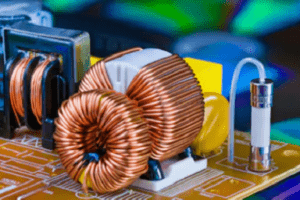
Transformer winding In electrical equipment with a specified function of a group of wires or coils known as the winding, for transformer products, usually will be connected according to the provisions of the single or several coils can change the voltage and current of the combination known as the winding, such as the primary winding, secondary winding.
The winding is the circuit part of the transformer, is an important part of the transformer. During the operation of the transformer, there is current passing through the windings, which will produce resistance losses, thus causing heat and reducing the efficiency of the transformer, but also may encounter overvoltage, high temperature . Overvoltage, high temperature, overcurrent and other adverse conditions. In order to make the transformer can be long-term safe and reliable operation, the transformer winding must meet the basic requirements of electricity, force and heat. Transformer winding conductor material is generally high conductivity copper and aluminium, conductor shape has round wire, flat wire and foil plate. Power transformers generally use flat copper conductors, round copper conductors are mainly used in small transformers and transformers, foil plate is mainly used for small and medium-sized transformers with a capacity of less than 2,000kV-A or less. According to the use of different insulation materials, the wire can be divided into paper winding line (referred to as paper winding line), enamelled winding line (referred to as enamelled line), silk winding line (referred to as silk winding line) and glass silk winding line (referred to as glass silk winding line).
The structure of the winding and the capacity of the winding, but also need to consider the degree of difficulty of processing and manufacturing. Commonly used winding structure in power transformers are double-layer cylindrical, multi-layer cylindrical, continuous, kinked, inserted capacitors within the shielded, spiral, foil, staggered cake type. Heart-type transformer generally use concentric structure, high and low voltage windings concentric set in the core column low voltage windings near the core column, high voltage windings set in the low voltage windings outside, high and low voltage windings as well as the windings and the core to be reliable insulation. High-voltage windings have many turns and fine wires, while low-voltage windings have fewer turns and thicker wires.


