The design steps for common transformer design projects can generally be summarized into the following four essential stages:
Step 1: Transformer Primary and Secondary Current Calculation and Simulation
- Current values can be obtained through calculation or simulation.
- Taking the flyback converter as an example, the primary current value can be determined by knowing the input voltage, duty cycle, and maximum input power, or it can be achieved through simulation software.
Step 2: Calculate Minimum Area Product ($A_p$)
After calculating the primary RMS current, the minimum Area Product ($A_{p, \min}$) can be calculated using the following formula:
Formula for Minimum Area Product ($A_{p, \min}$):
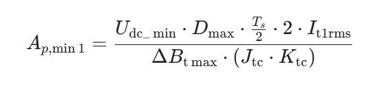
- The magnitude of $\Delta B$ (Flux Density Swing) depends on the core material.
- Empirical Values: Current density (J) typically ranges between 2 and 8, and the window utilization coefficient (K) is generally between 0.2 and 0.4.
The purpose of this step is to determine the minimum core area product required. Generally, the $A_p$ of the selected core model should be 1.2 to 1.5 times the calculated minimum value. Once the core model is selected, the effective area ($A_e$) and window area ($A_w$) are also obtained.
Step 3: Primary and Secondary Turns Calculation
This step is crucial for ensuring the appropriate voltage conversion ratio. The calculation methods and examples are as follows:
| Winding | Calculation Formula (Example) | Result |
| Primary Winding ($N_p$) | $N_p \ge \frac{I_{P_{\max}} \cdot L_p}{B_{\max} \cdot A_e} $ | $N_p \approx 207$ turns |
| Secondary Winding 1 ($N_{S1}$) | $N_{S1} = \frac{N_p \cdot (V_{OUT1} + V_{F_{\text{diode}}1})}{V_R}$ | $N_{S1} \approx 18$ turns |
| Secondary Winding 2 ($N_{S2}$) | $N_{S2} = \frac{N_p \cdot (V_{OUT2} + V_{F_{\text{diode}}2})}{V_R}$ | $N_{S2} \approx 25$ turns |
| VCC Winding ($N_{VCC}$) | $N_{VCC} = \frac{N_p \cdot (V_{VCC} + V_{F_{\text{diode}}VCC})}{V_R}$ | $N_{VCC} \approx 21$ turns |
Step 4: Air Gap Calculation Based on Magnetizing Inductance
A transformer core is designed to transfer magnetic energy, whereas an inductor core is designed to store magnetic energy.
- Purpose of Air Gap: Opening the air gap serves two purposes: preventing magnetic saturation and storing energy.
- Placement: Air gaps are usually located in the center leg of the core, while the outer legs should have minimal or no air gaps.
Skin Depth Consideration for Wires
- Definition: Skin depth is the distance the electric field penetrates a good conductor when its amplitude decays to $1/e$ (36.8%).
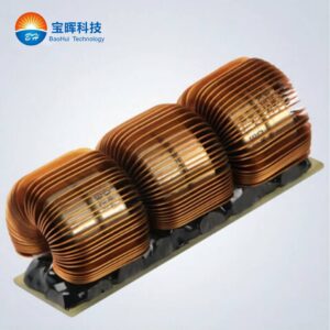
- Impact: Due to the skin effect, a single conductor wire cannot be too thick. To maintain current carrying capacity, multiple insulated wires must be used in parallel.
- Litz Wire: The diameter of Litz wire can be chosen to be twice the skin depth. Experience-based formulas for calculating skin depth at $20^{\circ}C$ and $100^{\circ}C$ are available.